Introduction: the flow limiter is also called damping, and it is widely used in hydraulic system circuits. the flow rate, adjust the speed and flow rate of the fluid. the main function is to reduce the shock of the hydraulic system circuit, stabilize the hydraulic pressure signal, and adjust the lubrication and cooling flow required by the branch circuit.
THREADED RESTRICTOR FLOW LIMITER
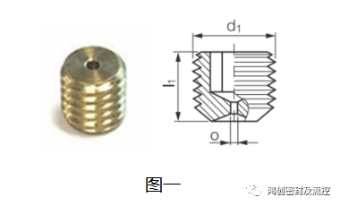
The traditional flow limiter is mainly a threaded flow limiter. as shown in figure 1, the outer diameter of this flow limiter is connected to the oil passage hole through threads, and the small hole inside plays the role of flow limit and damping. .
This threaded flow restrictor has the following disadvantages in practical application:
1. the inner hole of the oil passage needs to be threaded, and debris is generated during thread processing, and the debris falls in the staggered oil passages, which is very difficult to clean, and the debris will be processed in the subsequent work. in the middle oil circuit, it is easier to block the more precise hydraulic valve;
2. the thread restrictor is fixed with the oil passage through the external thread. the thread belongs to the connection function and does not have the sealing function. therefore, the oil in the oil passage often passes through the flow restrictor at this time, due to the sudden blockage, the pressure is bound to rise suddenly, and a small part of the oil flows through the threaded connection part instead of through the flow restrictor hole. in the practical test of the design of the small hole size of the flow limiter, it is very inappropriate. it is easy to grasp, especially for the precision oil circuit, it is more difficult to use the current limiter;
3. if this kind of threaded flow limiter wants to add a filter screen with filtering function in the hole, this structure is difficult to realize, and the filter screen cannot be added ;
4. often the outer diameter of this type of restrictor is relatively small, especially the deep hole thread processing of the oil channel is difficult, and the quality of the thread processing is often poor, resulting in timely tightening, coupled with the effect of high and low pressure fluid , the thread tightening force will become smaller, and there may be no problem at the beginning of the work, but after a stage of work in the hydraulic system, the flow limiter will fall off, causing the system to fail. to solve this problem, two threads are often screwed together back to back to play the role of thread locking, but in actual operation, the effect is also limited.
EXPANSION RESTRICTOR FLOW LIMITER

As shown in the figure above, this kind of current limiter pre-assembled by two parts is called an expansion type current limiter. Generally, this structure of the current limiter is composed of 2-3 parts, with small holes inside. it is the main body of the flow restrictor, and the upper part is similar to the role of the expansion pin for fixing. at the same time, according to the needs of customers, it can be equipped with a filter screen or without a filter screen structure. compared with the threaded restrictor, this restrictor has obvious advantages:
1. the oil channel hole does not need to be threaded, and the restrictor has tooth-shaped teeth, which are pressed in by pins to open the tooth-shaped teeth and holes the inner wall is occluded, so that there will be no processing debris on the restrictor in the entire oil passage, ensuring a clean oil passage;
2. for the processing of precision small restrictor holes, it can be processed efficiently and quickly automatically to ensure accuracy; then it is pre-installed together to facilitate large-scale and mass production;
3. additional filters can be added according to needs, and the filters can be arranged conveniently.
ADVANTAGES OF HC PRESSURE-EXPANSION RESTRICTOR FLOW LIMITER
1.1 processing consistency and quality control:
the main body of the current limiter adopts imported precision machining equipment, and the processing is completed in one clamping, which ensures the consistency of the product and the coaxiality of the flow limiting hole and the jacket. the tolerance of the flow limiting hole is controlled by +/-0.015.
3.2 small hole cleaning treatment:
due to the small size of the flow limiting hole, the burr is not easy to remove. the hole above 0.8 adopts magnetic deburring, and the hole below 0.8
special microporous deburring equipment is required to remove the burrs, and ultrasonic cleaning is performed after deburring to ensure the cleanliness of the product.
3.3 reliability of fixed performance with filter damping:
due to the needs of specific environments, a filter will be added to the damping. after adding the filter screen, we need to verify the withstand voltage reliability of the filter screen. in the withstand voltage test, we will block the filter screen or replace it with a metal sheet without filter holes. after normal assembly, we will conduct a withstand voltage reliability test. when the test pressure is 20mpa, the filter screen or metal sheet cannot fall off.
3.4 filter:

there are two types of metal screens on the market, one is made of steel wire, and the other is made of plate.
there is a defect in the filter mesh of steel wire weaving. when making a circular filter, the surrounding steel wires may fall off. in the subsequent assembly, the surrounding steel wires may also fall into the flow-restricting holes, affecting the filtering effect and the cleanliness of the entire flow restrictor is often difficult to control the cleanliness in some application fields with high cleanliness requirements.
there are three methods of plate processing filter: 1. drilling: but the cost is too high; the filter hole can be processed to 0.1 by laser drilling, and the filter screen processed by the plate can avoid the falling of the steel wire, which can better ensure the overall cleanliness of the current limiter;
the minimum size of the filter can be 0.075mm to meet the filtering needs of various application scenarios.
3.5 specifications of the restrictor and the range of the restrictor hole
hongchuang currently produces restrictors with outer diameters ranging from 4mm to 12mm, and restrictor hole sizes ranging from 0.1 to 6.0mm. various types of flow restrictors with and without filters can be customized according to customer requirements.
SMALL HOLE CALCULATION OF FLOW RESTRICTOR
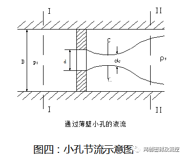
when the ratio of the flow length l of the small hole to the diameter d is less than or equal to 0.5, it is called a thin-walled small hole. as the picture shows. deduce the flow through the thin-walled hole: q=ac vc=cc a vc=cc cv a(2/ρδpc)1/2=cd a[(2/ρ)δpc]1/2
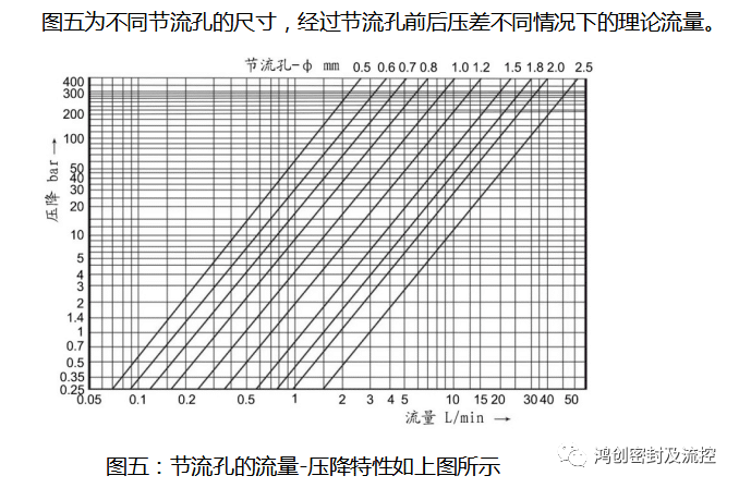
conclusion: the flow rate flowing through the small hole is proportional to the area of the small hole, and proportional to the root of the pressure difference before and after flowing through the small hole; it has nothing to do with the temperature; the calculation of the small hole is calculated based on the flow rate and the pressure difference before and after the small hole yes, but because of the influence of the flow coefficient, etc., in practice, we can roughly obtain the size of an orifice through software simulation, and then in practice, we gradually screen one by one according to the simulation results to select the optimal throttle. flowmeter orifice size.
DESIGN AND CALCULATION OF THE SERIES-PARALLEL CONNECTION SCHEME OF THE FLOW RESTRICTOR LIMITER
5.1 two orifices connected in parallel
flow distribution q1 /q2 = d1² /d2²
two orifices connected in parallel are equivalent to orifices: d=(d1²+d2²)^1/2
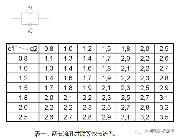
table 1: two orifices connected in parallel are equivalent to orifices:
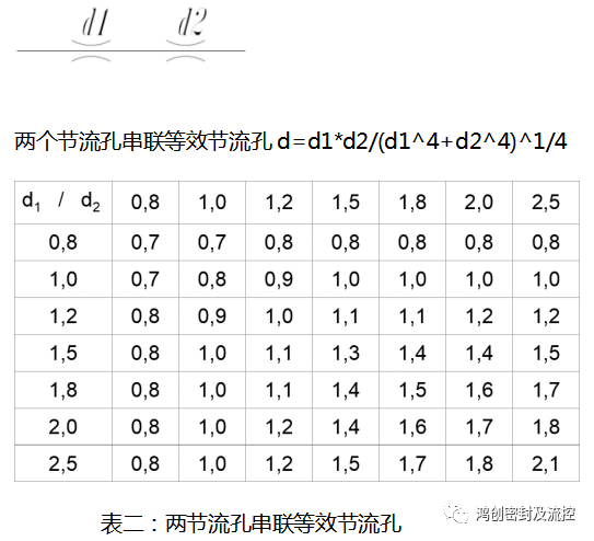
5.2 two orifices connected in series
differential pressure distribution △p1/ △p2 = d2^4 / d1^4
